
La capacità di leggere e comprendere i simboli di saldatura è molto importante nell'industria manifatturiera. Come altri aspetti del disegno, c'è una serie di simboli per la saldatura per semplificare la comunicazione tra progettista e costruttore (cioè il saldatore). In questo articolo discuteremo vari simboli di saldatura e il loro significato.
Cominciamo con i costituenti di un simbolo di saldatura. Di seguito è mostrato un tipico simbolo di saldatura.
Queste cifre rappresentano la struttura centrale di ogni specifica di disegno per una saldatura da eseguire. Il simbolo di saldatura ha una freccia che indica la posizione sul disegno in cui è richiesta una saldatura. La freccia è collegata a una linea direttrice che si interseca con una linea di riferimento orizzontale. Infine, c'è una coda all'estremità opposta della linea di riferimento che si biforca in due direzioni. La coda è facoltativa e necessaria solo per istruzioni speciali.
SIMBOLI TIPICI DI SALDATURA E LORO SIGNIFICATO:
1.) Il simbolo di saldatura può anche essere posizionato sopra la linea di riferimento, anziché sotto di essa. Questa posizione è importante. Quando il simbolo di saldatura è sospeso sotto la linea di riferimento, indica che la saldatura deve essere eseguita sul "lato freccia" del giunto. Ad esempio, nella figura mostrata di seguito, sul lato della freccia è specificata una saldatura d'angolo. Puoi vedere la saldatura effettiva nella seconda rappresentazione.
2.) Se il simbolo della saldatura appare sopra la linea di riferimento, allora la saldatura deve essere eseguita sul lato opposto del giunto dove punta la freccia. È rappresentato nella figura sottostante.
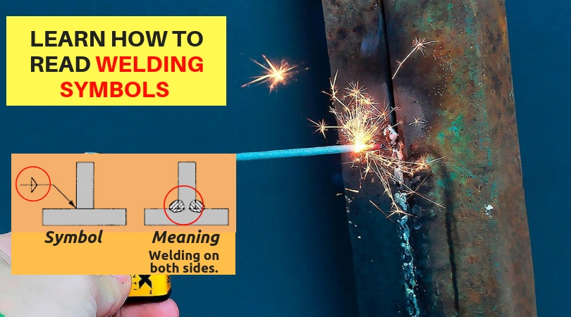
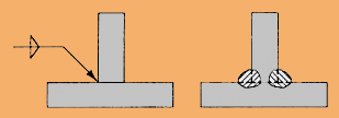
3.) Se il simbolo di saldatura appare su entrambi i lati della linea di riferimento, come mostrato di seguito, specifica che deve essere eseguita una saldatura su entrambi i lati del giunto. Questo è rappresentato nella figura sotto.
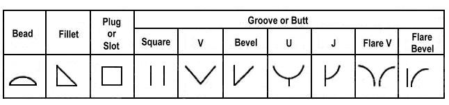
4.) Ogni tipo di saldatura ha il proprio simbolo di base, che in genere è posizionato vicino al centro della linea di riferimento (e sopra o sotto di essa, a seconda del lato del giunto su cui si trova). Il simbolo è un piccolo disegno che di solito può essere interpretato come una sezione trasversale semplificata della saldatura. Nelle descrizioni seguenti, il simbolo è mostrato sia nella posizione lato freccia che nell'altro lato.
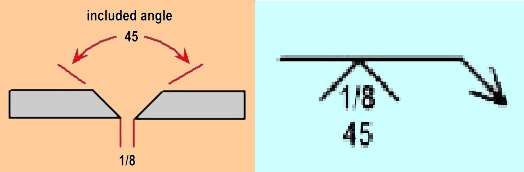
5.) Un simbolo di saldatura può anche specificare un angolo, un'apertura della radice o una dimensione della faccia della radice. Questo è comune quando il metallo di base da saldare è più spesso di 1/4 di pollice. L'esempio seguente è un simbolo e un disegno che richiedono un giunto con scanalatura a V:
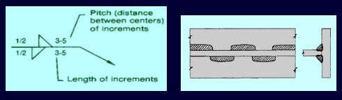
6.) A volte viene specificata una serie di saldature separate, anziché una singola saldatura lunga. Questo è comune quando vengono saldati metalli sottili o sensibili al calore, o dove il giunto è molto lungo. Nel seguente simbolo e disegno, le saldature d'angolo intermittenti da 3 pollici sono specificate e mostrate nella figura sottostante.
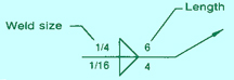
7.) Anche i numeri sono una parte importante di una specifica di saldatura. La larghezza, la profondità, l'apertura della radice e la lunghezza di una saldatura, così come l'angolo di qualsiasi smussatura richiesta sul metallo di base prima della saldatura, possono essere comunicati sopra o sotto la linea di riferimento.
Nella maggior parte dei casi, la larghezza (o diametro) della saldatura si trova a sinistra del simbolo di saldatura (qui espressa in pollici), mentre la sua lunghezza è scritta a destra. (La larghezza della saldatura è la distanza da un lato della saldatura all'altro.) Spesso non è indicata alcuna lunghezza, il che significa che la saldatura dovrebbe essere posata dall'inizio alla fine del giunto, o dove c'è un brusco cambiamento di il giunto sul metallo di base.
Le quote scritte sotto la linea di riferimento, ovviamente, si applicano al giunto sul lato della freccia, mentre le dimensioni scritte sopra si applicano al giunto sull'altro lato. Nell'immagine sopra, le saldature sono indicate per entrambi i lati del giunto.
8.) Coda facoltativa = Istruzioni speciali
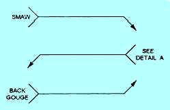
Come hai appena visto nel caso della striscia di supporto, la coda biforcuta del simbolo di saldatura viene utilizzata per trasmettere dettagli che non fanno parte dei normali parametri dichiarati sulla linea di riferimento. Ad esempio, l'ingegnere o il progettista potrebbe volere che il saldatore utilizzi una saldatura specifica (ad esempio SMAW) o un altro processo di saldatura. Oppure ci possono essere altre informazioni da trasmettere:
Naturalmente, quando non sono necessarie istruzioni speciali, la coda viene omessa dal simbolo di saldatura, lasciando solo la linea di riferimento, la freccia e la linea direttrice.
Oltre a questi, ci sono altri simboli ma questi sono alcuni dei simboli obbligatori che ogni specifica di saldatura contiene.
Se trovi utile questo articolo, condividilo con i tuoi amici e se vuoi aggiungere qualcosa non esitare a scrivere nella casella dei commenti.
Scarica questo articolo.
The ability to read and understand weld symbols is very important in the manufacturing industry. Like other aspects of drafting, there’s a set of symbols for welding to simplify the communication between designer and builder (i.e. the welder).In this article, we will discuss various welding symbols and their meaning.
Let us begin with the constituents of a welding symbol. A typical welding symbol is shown below.

These figures represent the core structure of every drafting specification for a weld to be performed. The welding symbol has an arrow, which points to the location on the drawing where a weld is required. The arrow is attached to a leader line that intersects with a horizontal reference line. Finally, there's a tail at the opposite end of the reference line that forks off in two directions. The tail is optional and needed only for special instructions.
TYPICAL WELDING SYMBOLS AND THEIR MEANING :
1.) The weld symbol may also be placed above the reference line, rather than below it. This placement is important. When the weld symbol hangs below the reference line, it indicates that the weld must be performed on the "arrow side" of the joint. For example, in the figure shown below, a fillet weld is specified on the arrow side. You can see the actual weld in the second depiction.
![]()
2.) If the weld symbol appears on top of the reference line, then the weld should be made on the opposite side of the joint where the arrow points.It is represented in the figure below.
![]()
3.) If the weld symbol appears on both sides of the reference line, as shown below, it specifies that a weld must be performed on both sides of the joint. This is represented in the figure below.
4.) Each type of weld has its own basic symbol, which is typically placed near the center of the reference line (and above or below it, depending on which side of the joint it's on). The symbol is a small drawing that can usually be interpreted as a simplified cross-section of the weld. In the descriptions below, the symbol is shown in both its arrow-side and other-side positions.
5.) A weld symbol may also specify an angle, root opening or root face dimension. This is common when the base metal to be welded on is thicker than 1/4 inch. The following example is a symbol and drawing calling for a V-groove joint:
6.) Sometimes, a series of separate welds is specified, rather than a single long weld. This is common when thin or heat-sensitive metals are welded on, or where the joint is a really long one. In the following symbol and drawing, 3-inch intermittent fillet welds are specified and shown in figure below.
7.) Numbers are also a big part of a welding specification. The width, depth, root opening and length of a weld, as well as the angle of any beveling required on the base metal before welding can all be communicated above or below the reference line.
In most cases, the weld width (or diameter) is located to the left of the weld symbol (expressed here in inches), while its length is written to the right. (The weld's width is the distance from one leg of the weld to the other.) Often, no length is indicated, which means the weld should be laid down from the beginning to the end of the joint, or where there's an abrupt change in the joint on the base metal.
Dimensions written below the reference line, of course, apply to the joint on the arrow side, while dimensions written above apply to the joint on the other side. In the image above, welds are indicated for both sides of the joint.
8.) Optional Tail = Special Instructions
As you just saw in the case of the backing strip, the forked tail of the welding symbol is used to convey details that aren't part of the normal parameters declared on the reference line. For instance, the engineer or designer might want the welder to use specific welding ( for example SMAW), or another welding process. Or there may be other information to convey:
Of course, when no special instructions are needed, the tail is omitted from the welding symbol, leaving just the reference line, arrow and leader line.
Apart from these, there are other symbols but these are some of the mandatory symbols that every welding specification contains.
If you find this article helpful kindly share it with your friends and if you want to add something to it feel free to write in the comment box.
Download this article.

- Log in to post comments